SYNTHESIZERS
Synthesizer I
How to Build a Voltage Controlled Oscillator (VCO) with a 555 Timer Chip
Credits: https://www.learningaboutelectronics.com/
Explore The Images
Theory and Process
01.
Idea & Concept
A voltage-controlled oscillator (VCO) is dynamic because we can vary the frequency of the digital signal just by changing the input voltage. So we can get a wide range of frequencies just by changing the voltage. So it's like a variable crystal oscillator.
02.
Design & Production
The 555 timer requires a power supply voltage of 4.5-16V. We connect this voltage to the VCC pin, pin 8, and we connect GND, pin 1, to ground. The only other pins we use are the trigger pin, the output pin, the reset pin, and the threshold pin. Pin 2 is the trigger pin. It works like a starter pistol to start the 555 timer running.
03.
Design & Production
Pin 3 is the output pin. 555 timer's output is digital in nature. It is either high or low. The output is either low, which is very close to 0V, or high, which is close to the supply voltage that's placed on pin 8. Pin 4 is the reset pin. This pin can be used to restart the 555 timer's timing operation.
04.
Design & Production
Pin 5 is the control voltage pin. To this pin, we connect a potentiometer to. One end of the potentiometer is connected to positive voltage and the other end is connected to ground. By varying the potentiometer resistance, we change the voltage input into this pin. Pin 6 is the threshold pin. The purpose of this pin is to monitor the voltage across the capacitor that's discharged by pin 7.
05.
Analysis
You should connect a capacitor in parallel to this DC source of power. The capacitor serves to clean up noise from the DC power source so that the output square wave signal produced by the 555 timer isn't as noisy.
06.
Analysis
When the voltage is high, the frequency is low. As we decrease the voltage to the control voltage pin, the frequency increases. If you want to increase the frequency of the output signal, you can decrease either the resistor or capacitor in the RC network. So, for example, you can change the 33KΩ with a 10KΩ resistor. This will significantly increase the frequency.
Breadboard Simulation
Synthesizer II
Astable Multivibrator – The Easiest Synthesizer in the World
Credits: Cicles Formatius Departament de Telecomunicacions
The Theory
The Process
01.

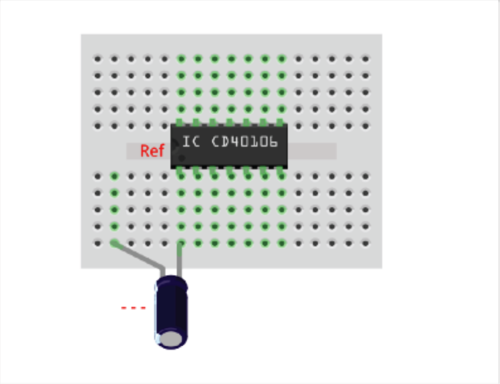
Place the IC and the capacitor.
02.

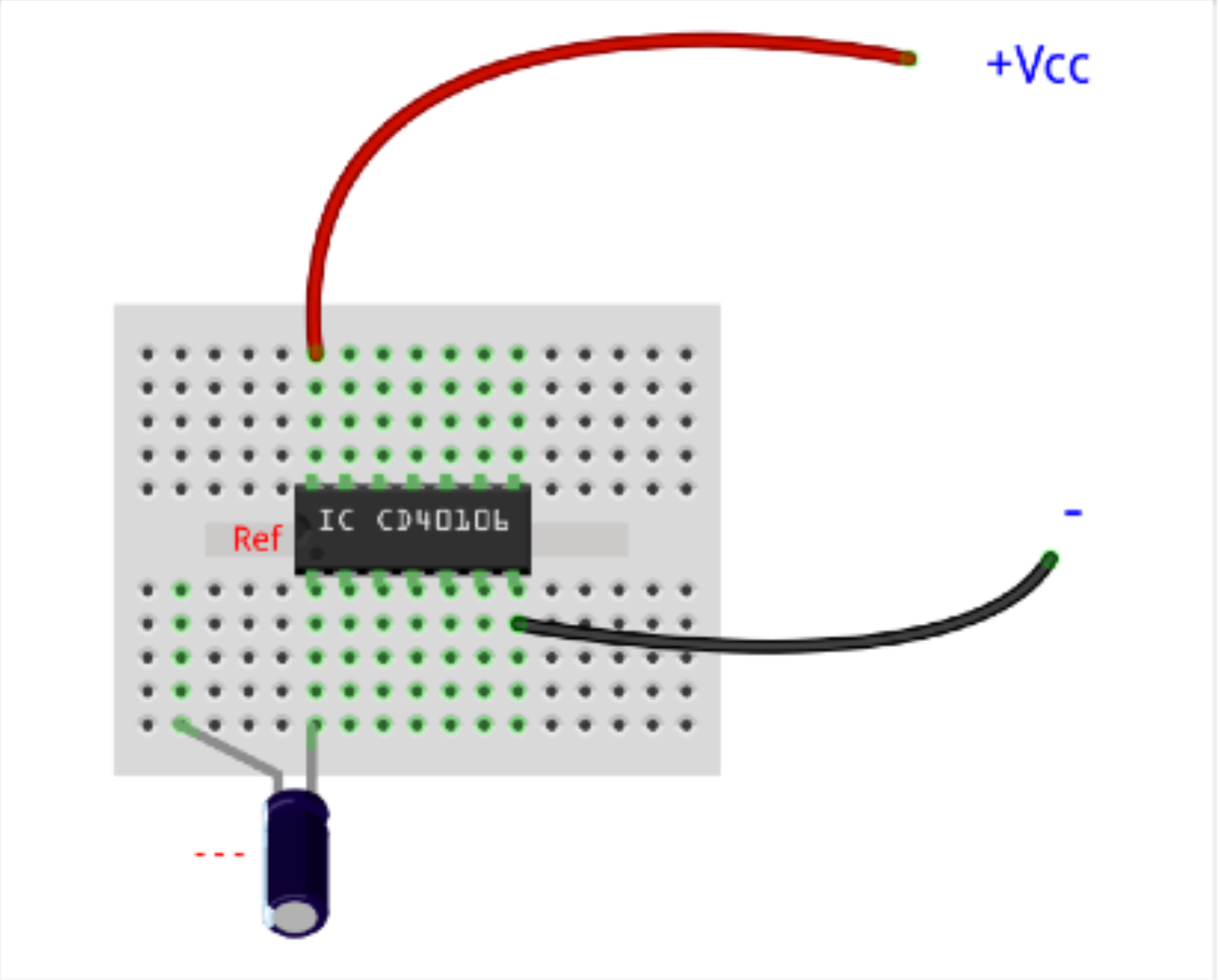
Connect the Power Supply wires.
03.

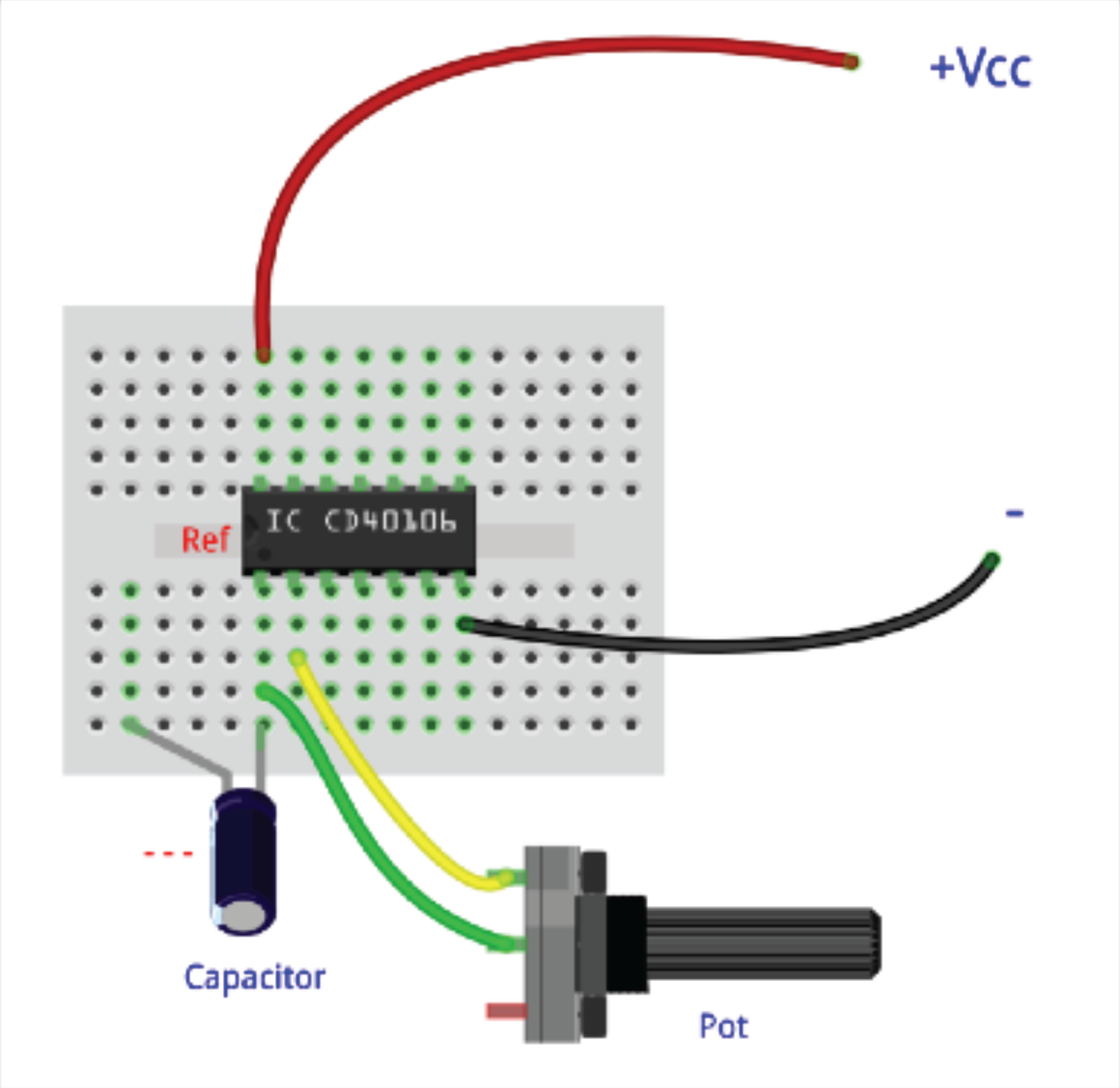
Place and connect the potentiometer.
04.
