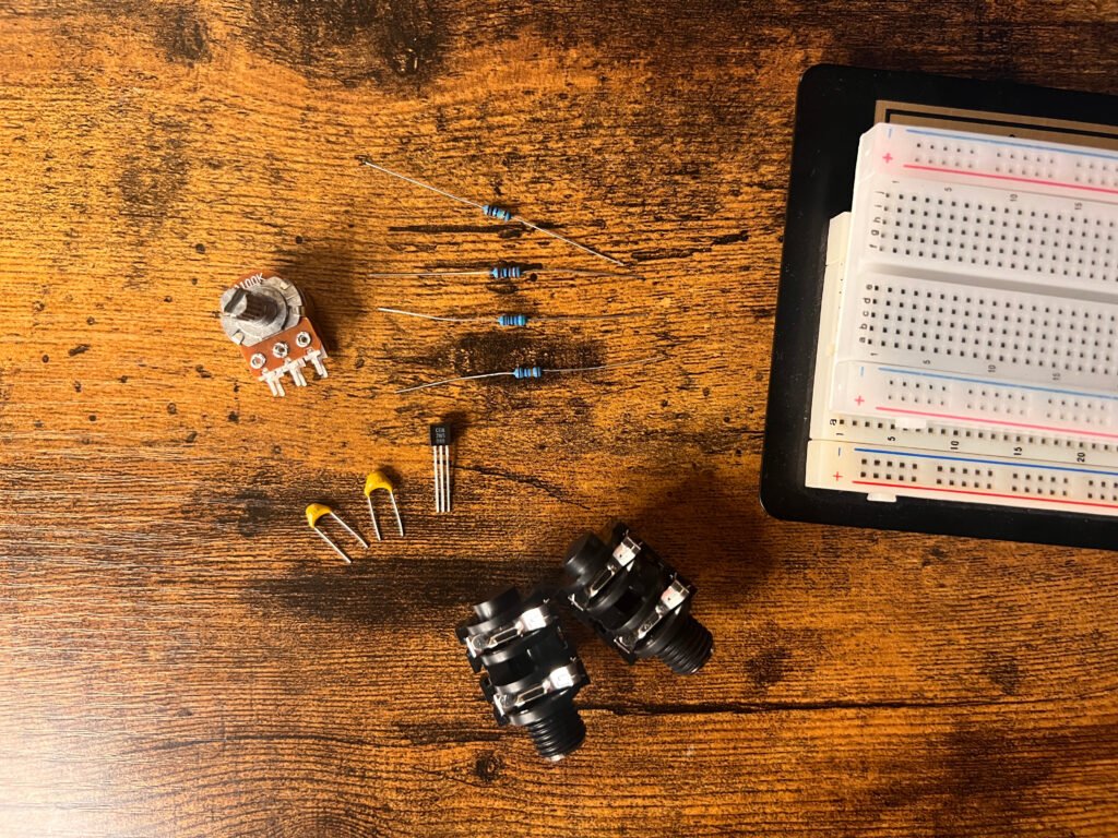
Two PCB Panel Mount 4 Pin 1/4" Mono Female Sockets
Breadboard
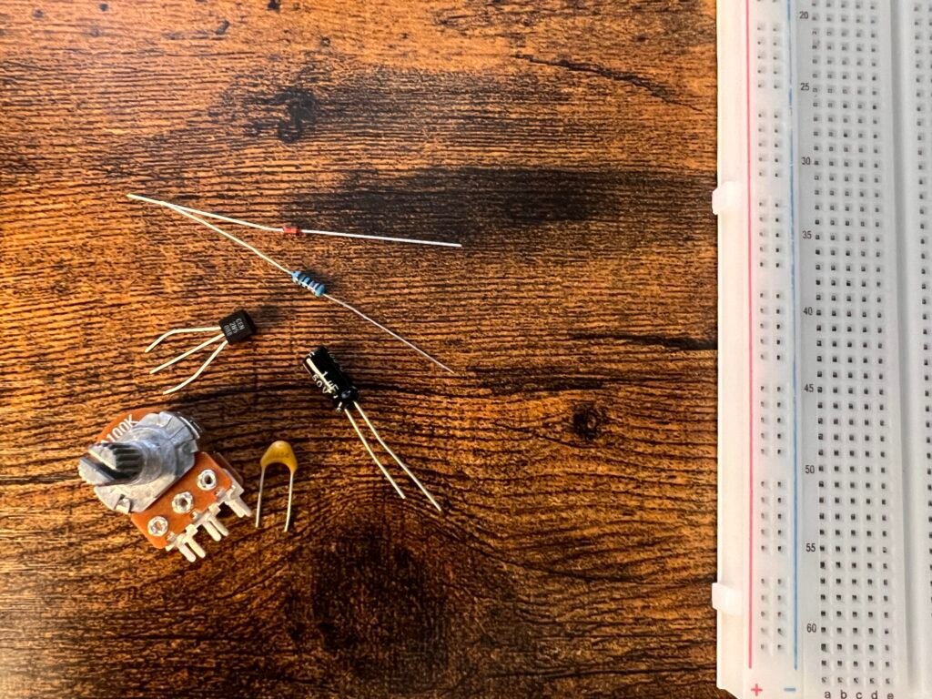
Fig. 1: Materials
Made a few subsitutions noted above. Including:
Substituting the MPSA13 for the 2n5088, which are both Beta transistors. So, no real difference there.
Substituting the ceramic (105) capacitor for the polarized electrolytic cap.
Substituting the Schottky BAT41 diode for the Silicon 1N4148 diode. The forward voltage drop for silicon diodes is approximately 0.7 Volts. The forward voltage drop for Schottky diodes is approximately 0.3 Volts. This means that the Schottky diode will start conducting sooner for many waveforms. The lower the value of forward voltage the greater the degree and onset of distortion. So, the Schottky circuit has very high distortion by clipping sooner with maximum compression as compared to the Silicon which has more of a classic overdrive and distortion with some degree of compression. The ability of the Schottky diode to handle very high frequencies actually resulted in it detecting/de-modulating AM Radio frequencies which were amplified by Q1 and fed to the output.
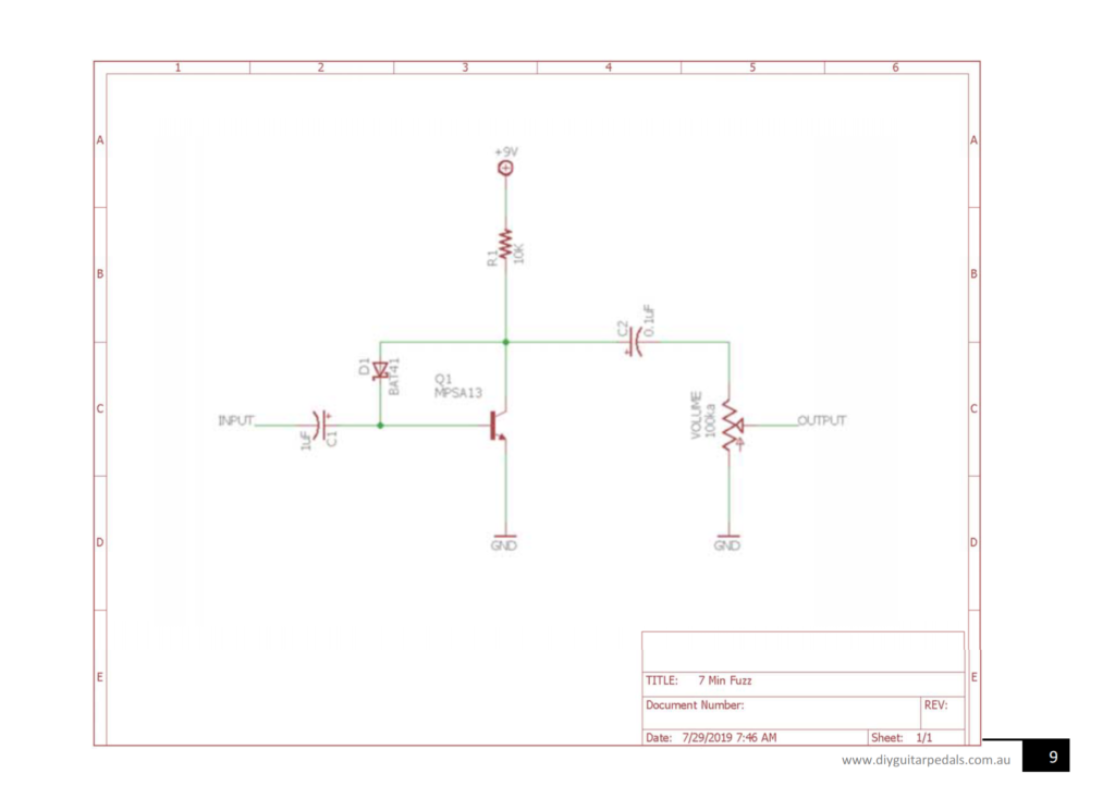
Fig. 2a: Schematic
Fig. 2b: Circuit Analysis
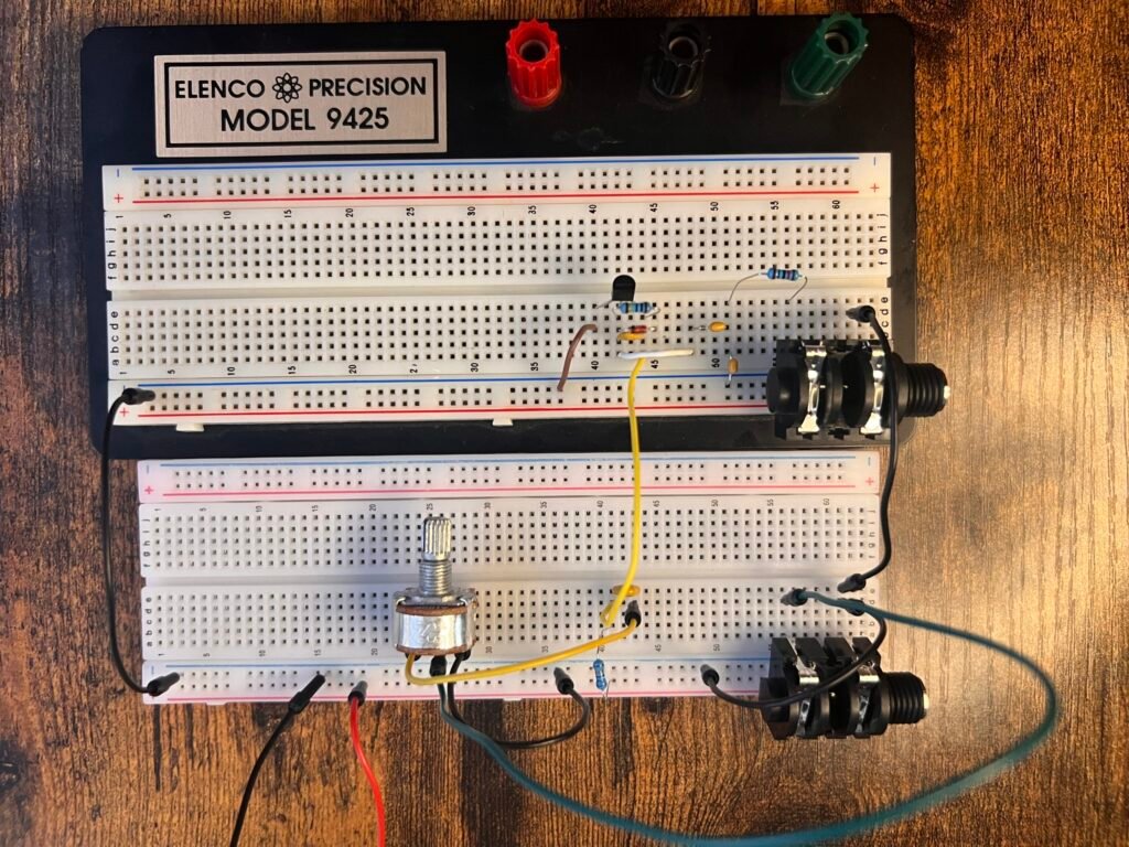
Fig. 3a: Breadboard Wiring
Fig. 3b: Breadboard Wiring, Cont'd
Pedal II - Distortion
Distortion Pedal Circuit in a Few Minutes
Credits: https://tonecharmaudio.com/
Bill of Materials Needed
(R1) 1MΩ
(R2) 10KΩ
(R3) 100KΩ
(Q1) 2n3904
(D1) 1N4148
(C1) 180pF [181]
(C2) 15nF [153]
(C3) 47pF [470]
(C4) 100nF [104]
(POT) A100K
Two PCB Panel Mount 4 Pin 1/4" Mono Female Sockets
Breadboard
Fig. 1: Materials
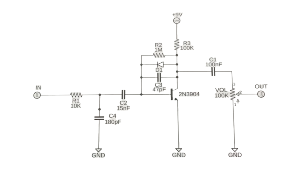
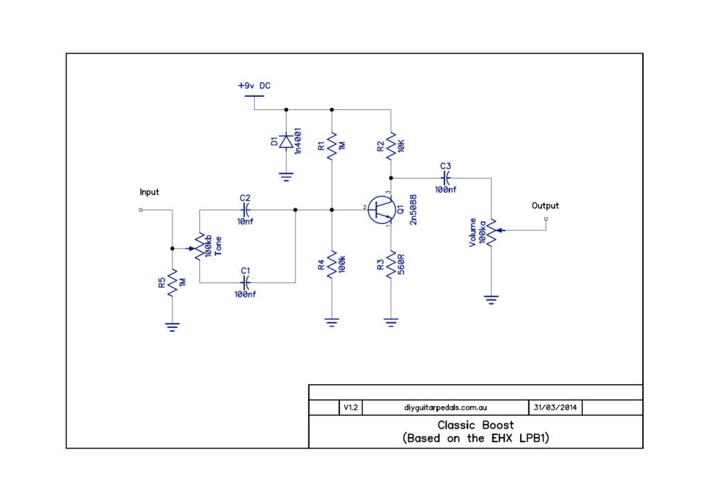
Fig. 2: Schematic
Fig. 3: Wiring
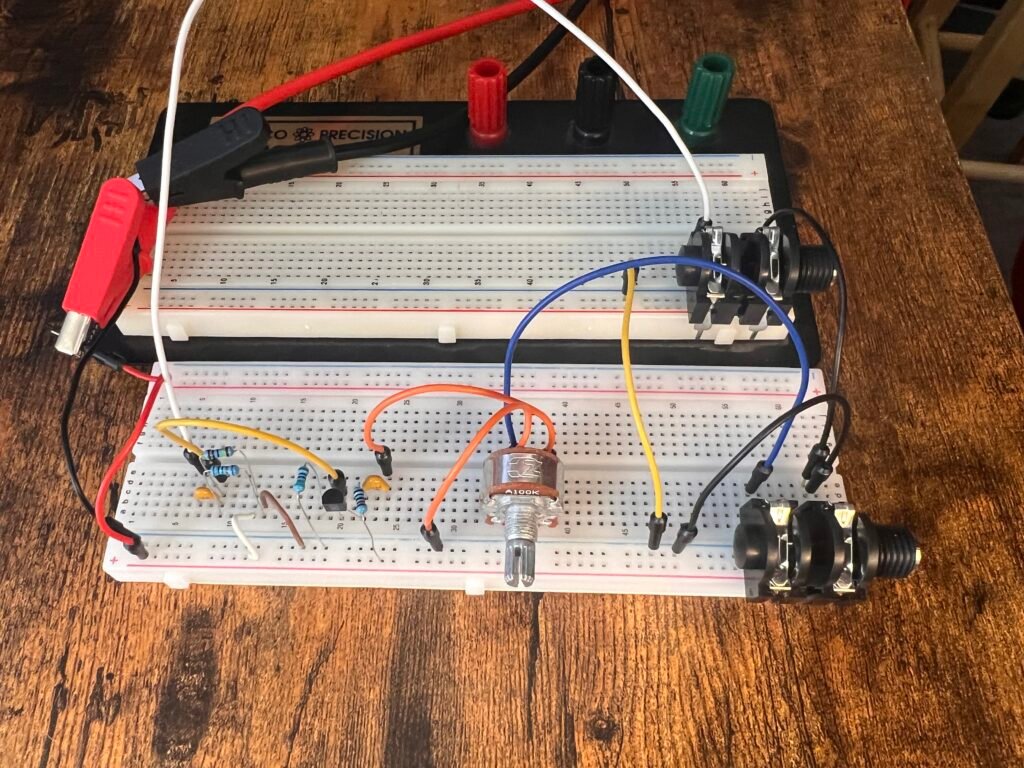
Fig. 4a: Breadboard Wiring
Fig. 4b: Breadboard Wiring, Cont'd
Pedal I - Classic Boost
The Classic Boost is a dirty transistor boost based on the EHX LPB1™.
Credits: diyguitarpedals.com.au
Bill of Materials Needed
(R1) 1MΩ
(R2) 10KΩ
(R3) 560R
(R4) 100KΩ
(U1) 2n5088
(C1) 100nF [104]
(C2) 100nF [104]
(POT) A100K
Two PCB Panel Mount 4 Pin 1/4" Mono Female Sockets
Breadboard
Fig. 1: Materials
Got rid of the tone control on the front to make things easier
R5 is the input pulldown/ground reference
So, the input goes directly through the capacitor C1 then straight into the base of the transistor
Basically, creating an electro harmonix lpb-1 boost pedal; the tone control is just a mod
The diode is not necessary on a breadboard but rather for pcb; it is reverse polarity in case you plug ground into power and power into ground. The diode will bypass the circuit, so you don’t damage anything in the circuit