Mark I Trigger Pad
The Mark I
Drum Trigger Pad
Market Need
Process
Step 1: Sketch
Simply sketch the idea on paper
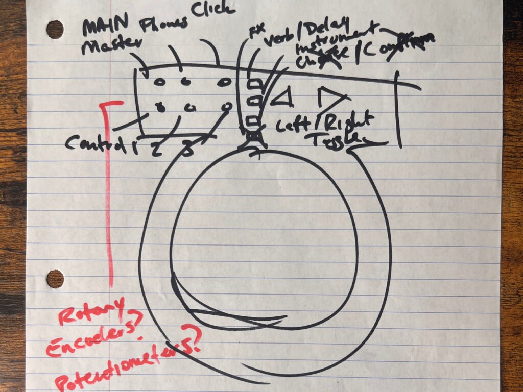
Initial Sketch
The initial sketch shows the thought process: the single trigger pad along with the controls. I have to decide the controls I want, which offer a wide range of plug-in controls with the least amount of components used.
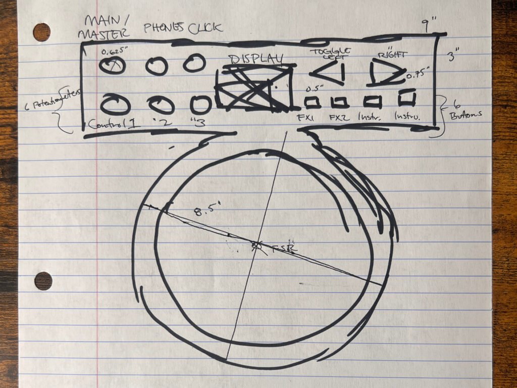
Revised Sketch
Here is a revised sketch with the component placement a little more finely tuned. I considered a display, but I decide to leave that for Mark II. At this point, the only thing I want to change is not having the trigger pad enclosure be bound to the circuitry component enclosure. This is because resonance may be an issue when playing, because the trigger pad is not isolated. I may revisit this change if the practical resonance effect is close to negligible, especially if a single enclosure dramatically affects a price point.
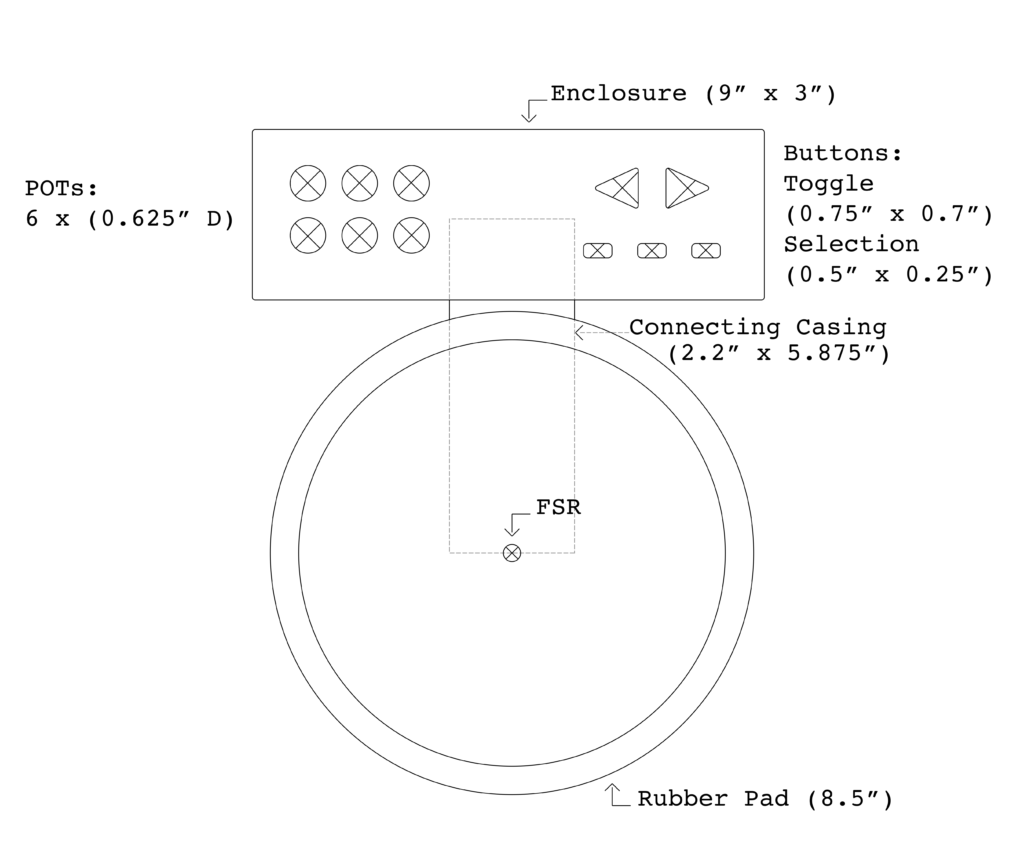
Trigger Pad Parametric Design Mock Up
All major enclosures and casings are shown with components oriented and placed. Dimensions are specified.
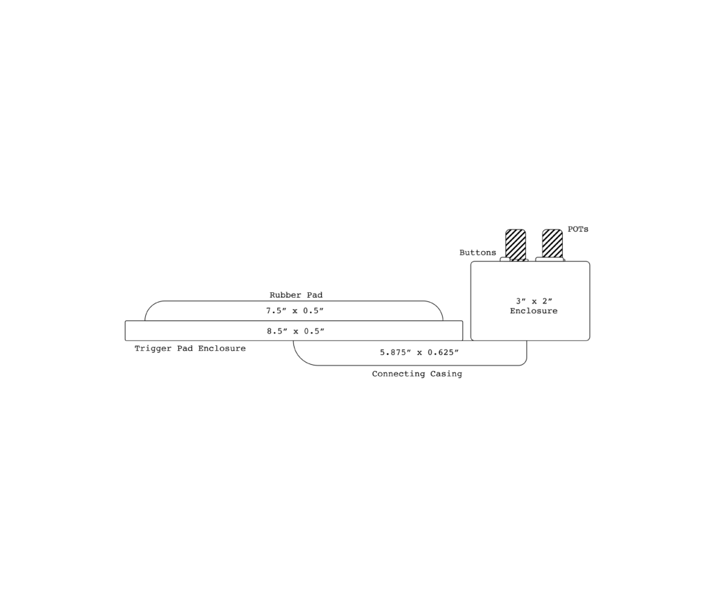
Trigger Pad Mock Up (Side View)
Here, it is important to note the enclosure for the processor and circuitry components could be altered. The height could be greatly decreased on a reprint if the processor can be positioned flat within the enclosure. Without mounting and soldering, I am not sure of how the enclosure will hold all of the parts.
Step 2: Choosing the Components
Specify all digital or analog inputs and outputs and which kind used
Deciding on which materials to use is fairly simple after knowing what assignable controls I want. I will use two toggle buttons, three program change buttons (five buttons in total), and six control change rotary potentiometers controlling effect and decibel levels. The buttons are digital inputs, while the potentiometers are analog.
The chain of events needed to hit a pad and make a drum module play a sound is simple:
1) Hit the pad
2) Drum module trigger input reads the trigger waveform
3) The drum module interprets the trigger waveform and sends the assigned sound to the audio output
So next, I have to decide the trigger component. There are two main options. A piezo disc sensor, or a force sensing resistor (FSR).
A lot of pads and triggers on the market use piezo technology to make them work. A piezo is a crystal that has the property of producing voltage when it is put in motion. In this case, we put the piezo in motion by striking something to which it’s attached or coupled. This could be a rigid plate in a pad, or a drumhead of some kind. We do this because a piezo is very fragile, striking it directly will destroy it rather quickly. Many clever ways have been devised and patented to protect the piezo, while at the same time offering adequate triggering performance. In addition to piezos, there is also increasing use of FSR technology – force-sensing resistors – in pads and acoustic triggering.
So what are the key differences?
Piezo Disc Sensor
- Has high impedance and very capacitive
- They are inexpensive to make and can be easily applied to many different surfaces
- Many advantages in terms of ease of use, cost, and longevity
- But they are not capable of maintaining a DC signal, as they have internal leakage which will drain off the charge induced by the applied force
- High source impedance, making them susceptible to picking up noise
- Exhibit responses to both light and heat
Force Sensing Resistor (FSR)
- Has a wide range of resistance
- A fairly inexpensive and easy to implement means of measuring an applied force
- Less sensitive than piezo discs, so it can sense whether a touch is accidental or intentional by a reading force
- They vary with time, temperature, and loading conditions, which make them inaccurate and unrepeatable, but for prototyping an idea quickly, they can be a good solution
In the end, I chose the FSR in my circuit because of all the things the piezo is not. First, it is not overly sensitive. For a drummer, the fact the sensor can differentiate between accidental touches is important. Second, the FSR does not pick up noise easily. Third, the FSR does not have a small range of resistance. It has a wide range of resistance, which allows for the user to be able to trigger the same note at different amplitudes when there is a change in force applied.
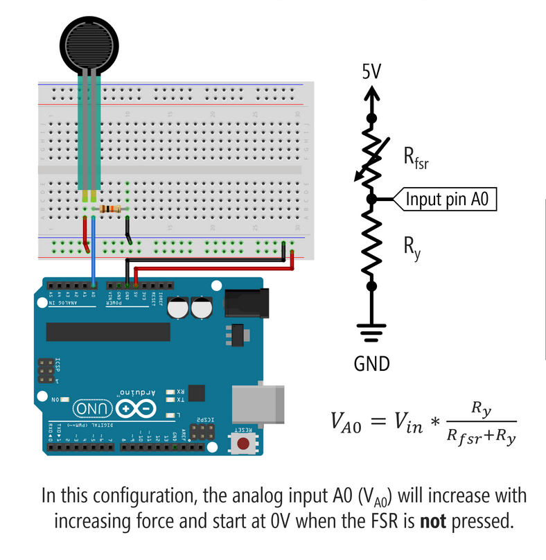
All that is left is to choose the fixed resistor value for the voltage divider necessary for the functionality of the FSR. To use an FSR, you must add a fixed measuring resistor to form a voltage divider because the microcontroller can only read changes in voltage and not current. That is, when a second resistor is added in series we can control the analog input to the microprocessor, which is the voltage at the terminal in between both resistors. This control happens when we control the variable resistance of the force sensing resistor by applying a pressure force to the resistor. In a simple FSR circuit configuration with the fixed resistor in the pull-down position, the analog input A0 (VA0) will increase with increasing force and start at 0V when the FSR is not pressed.
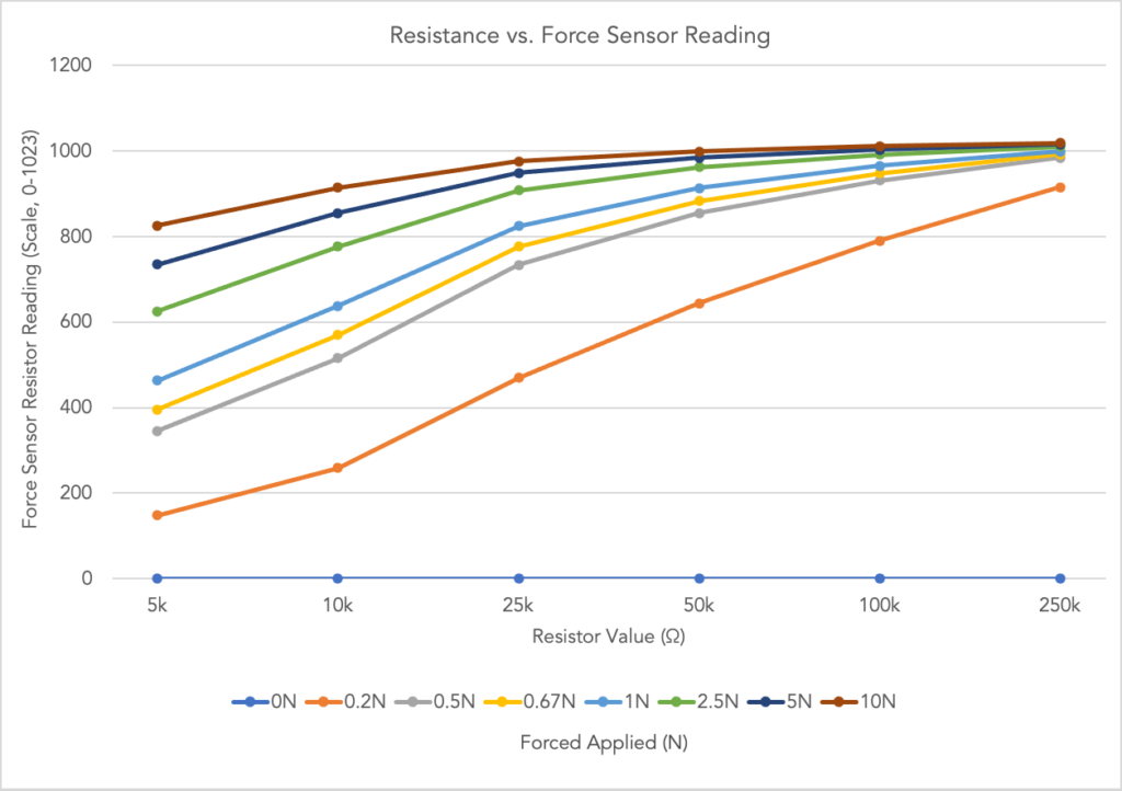
Consideration is given when choosing the value of the fixed resistor. The value is chosen to maximize the desired force sensitivity range and to limit current. After this threshold, the FSR resistance becomes inversely proportional to the applied force. I created the circuit shown and ran a test with various fixed resistor values, testing for two conditions: the greatest spread of FSR readings and the largest resistor value so that we have the smallest operating current for the FSR. I choose a 10kΩ resistor because it best fit both conditions.
Materials used
- (6) Linear 10kΩ Rotary Potentiometers
- (5) Small On/Off Buttons
- Force Sensor Resistor
- 10kΩ Resistor
Step 3: Choosing the Microprocessor
Specify the processor we will use
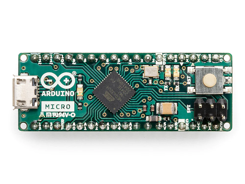
Arduino Micro
At first, I had 13 inputs (7 analog and 6 digital). Then I changed my mind to use only 6 analog inputs, since the Arduino Uno I’m testing with has 6 analog pins and I wanted to avoid using multiplexers. However, I later realized that one of those analog pins needs to be reserved for the force-sensitive resistor (FSR), which means I only have 5 available for potentiometers. In the final design, I’ll use the Arduino Micro, which provides the necessary number of digital and analog inputs within a compact board size. So this is an important thing to note as we move forward—only five potentiometers will appear in the current design, which differs from the original plan. To help make up for this loss in functionality, I’m adding an additional push button to expand user interaction in a different way.
Step 4: Design circuit in circuit design software
Using an electronics design and prototyping platform, we can prototype the project
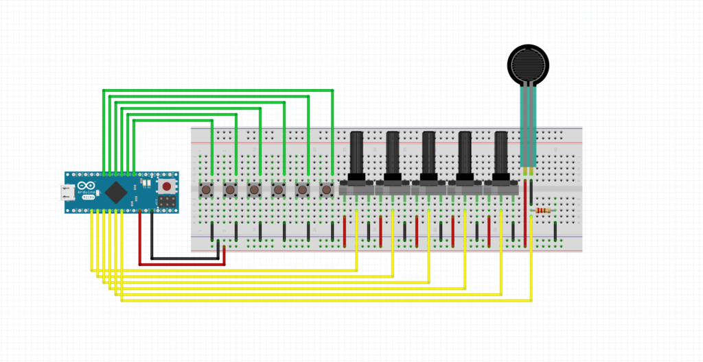
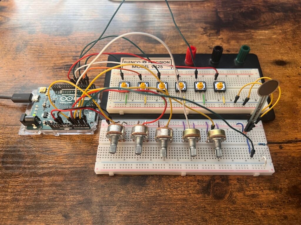
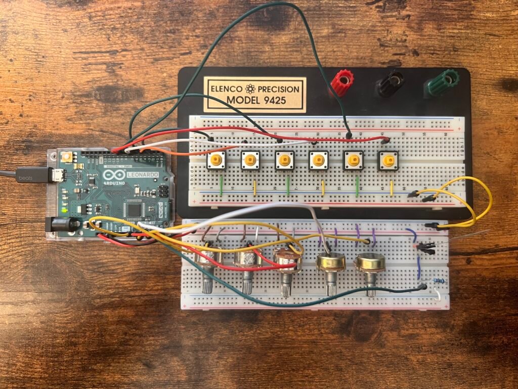
Prototyped Circuit in Fritzing
Breadboard prototype setup with six buttons connected to digital inputs, and five potentiometers and a force sensing resistor connected to six analog inputs.
Breadboard Simulation
Running a simulation on Tinkercad to test the output readings across the circuit.
Step 5: Build the prototype Circuit
Using an electronics design and prototyping platform, we can prototype the project
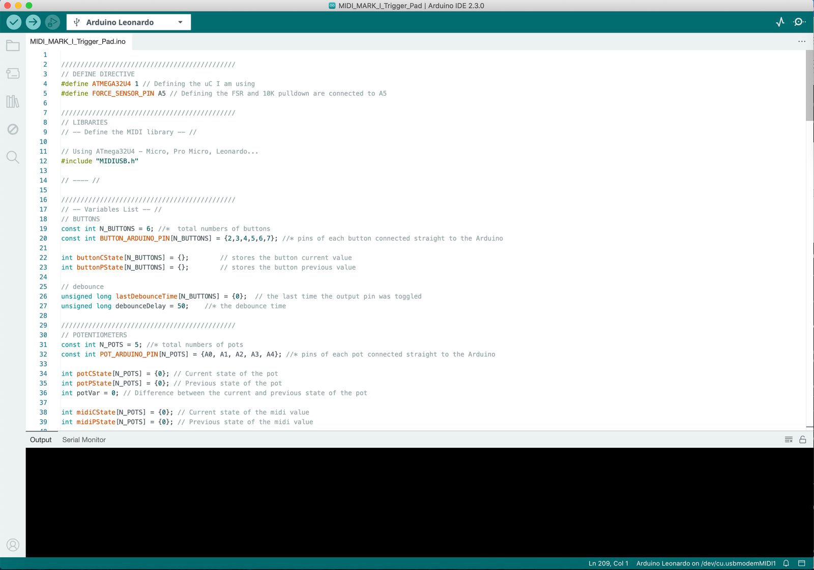
Step 6: Program the Circuit
Write and confirm the working code to program the circuit
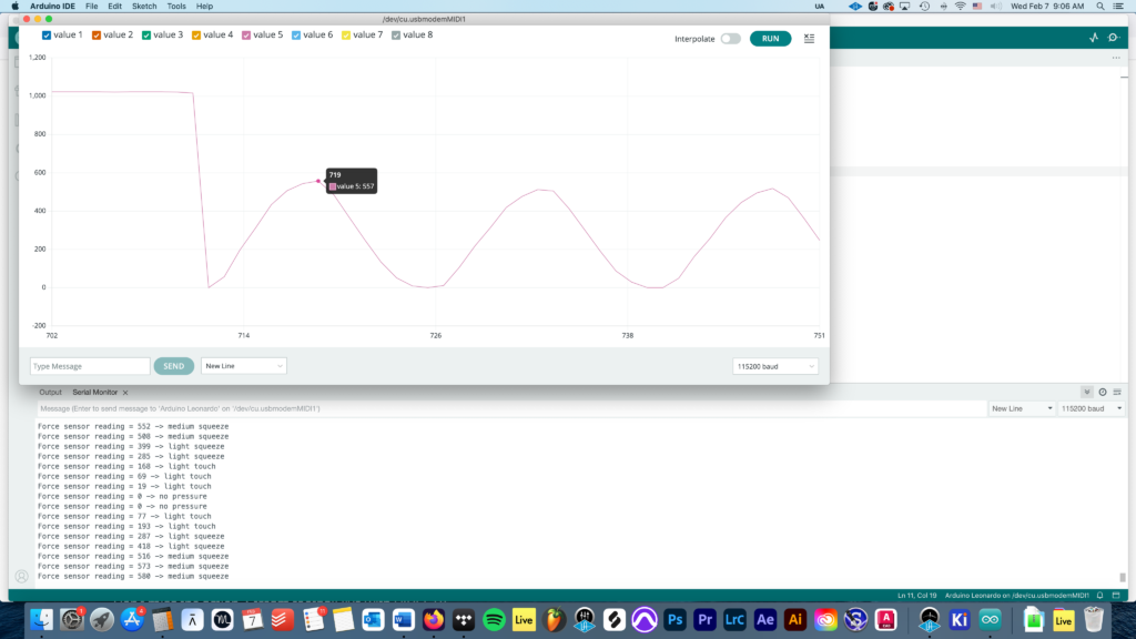
Below shows the Arduino IDE serial monitor showing output values and the serial plotter showing a graphical representation, where I have isolated the output produced by the FSR. You can see that for some reason, the FSR’s reading produces a sine wave output result ranging from 0-600 when left idle and no force is given to the component. When the threshold of pressure needed to activate the FSR is exceeded, the FSR produces a constant result. However, even with the smallest force applied the result always reaches its threshold for the sensor reading. Shown by the constant maximum value on the Y-axis on the serial plotter.
Step 7: Design & build enclosure, parametric design
Create a 3D parametric model
In the middle of finishing my 3D design…
Step 8: Design PCB
Create the schematic and design of electronic hardware for PCB manufacturing
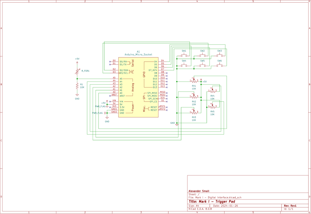
Schematic Diagram
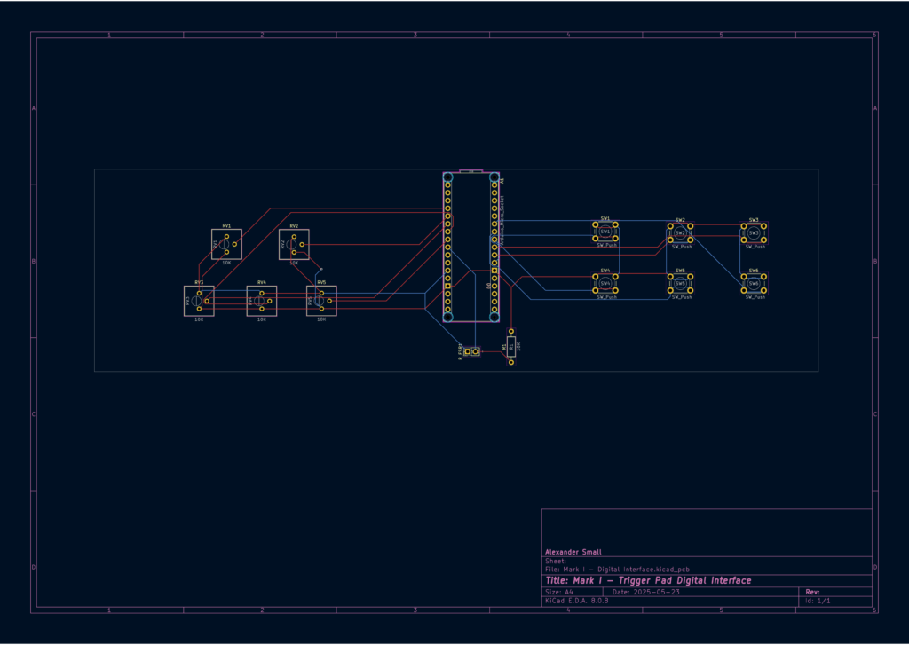
PCB Layout (2D View)
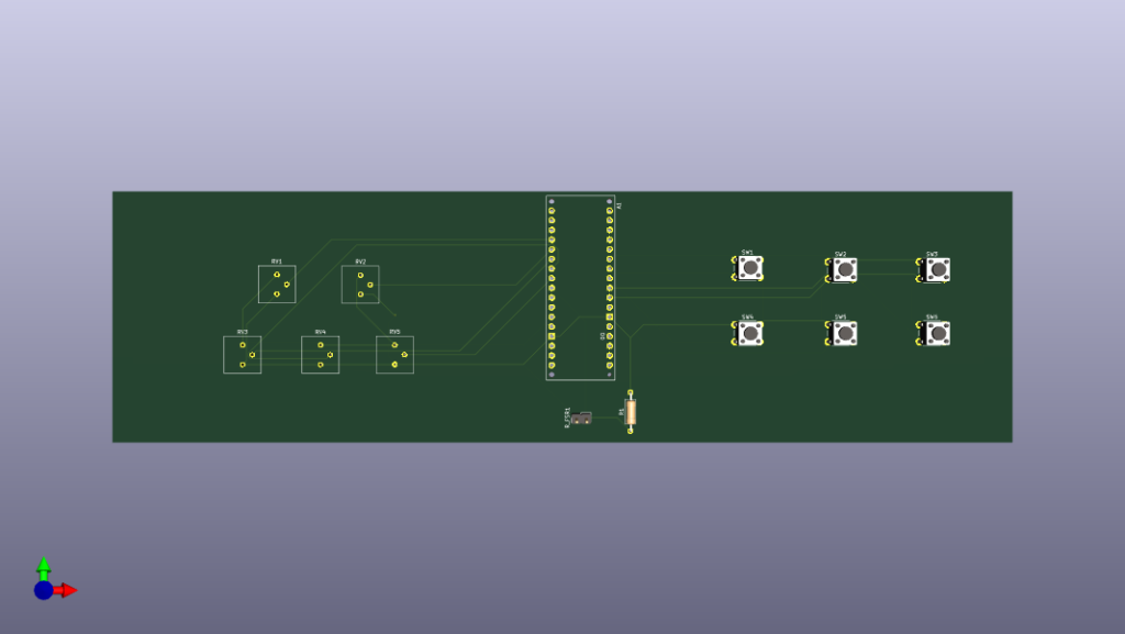
3D PCB Render
Step 9: Mount & Solder
Step 10: Configure, Test, Play
I will complete step 9 and 10 after all modeling is printed and ready to be assembled…
Credits:
- https://go.musiconerd.com/nerd-musician-pro
- Ten step process
- https://www.youtube.com/watch?v=6NWJc3xfEj4
- Materials, FSR vs. Piezo Trigger, Thought process
- https://www.youtube.com/watch?v=u2EHDyrV_F0
- Building a Drummer trigger using an FSR
- https://drummagazine.com/dont-pull-that-trigger-2/
- FSR vs Piezo Sensor Drum trigger history
- https://courses.media.mit.edu/2022spring/mas836/problem_sets/ps3.pdf
- FSR vs Piezo Sensor characteristics
- https://makeabilitylab.github.io/physcomp/arduino/force-sensitive-resistors.html
- FSR and load resistor creating a voltage divider.